in our previous articles we present the ASME code and its section VIII called “Rules for Construction of Pressure Vessels”. We also commented that this section is composed of 3 divisions and we present the main differences between Divisions 1 and 2. In today's article we will deal with Division 3 of the code.
Division 3 is applicable for equipment subjected to high pressures. In Division 2, paragraph 1.2.2.2, it is suggested that for pressures greater than 68.95 MPa (10,000 psi) Division 3 of the code be used.
Generally speaking, it can be said that Division 1 should be applied for pressures up to 20 MPa (approximately 3000 psi), Division 2 from 20 MPa up to 69 MPa (from 3000 psi to 10,000 psi) and Division 3 for pressures above 69 MPa (10,000 psi). Note that this is not an obligation of the code and any Division can be used for any pressure provided that due care is taken with its application.
Division 3 does not have a defined allowables table and uses the yield and rupture stress values of the materials at the design temperature (ASME Section II, Part D Y-1 and U tables).
As a simple example for illustrating the difference between Code Divisions, consider a 1000 mm internal diameter cylinder, manufactured in SA-516-70, subjected to an internal design pressure of 10 MPa, with a design temperature of 200ºC, a welding efficiency equal to 1.0 and without any corrosion margin. Under these conditions we would have, in the case of each of the Code Divisions, the following calculated thicknesses, far from discontinuities:
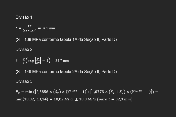
It can be seen that the calculation using the Division 1 formula (37.9 mm) entails the greatest thickness required for the cylinder, as discussed above. The formula applicable by Division 3 is the one that implies the smallest thickness (32.9 mm).
A very interesting aspect of Division 3 is the Fracture Mechanics analysis. The number of allowable cycles in analyzes for cyclic loads can be obtained by the traditional fatigue analysis, presented in paragraph KD-3 (similar to the fatigue analysis presented in Division 2 of the code), or by the crack propagation analysis, using the concepts of fracture mechanics as presented in paragraph KD-4.
In KD-140 the code states that a traditional fatigue analysis can be performed if the leak-before-burst phenomenon (in a loose translation, “leak before burst”) can be demonstrated for the equipment. Otherwise, fatigue analysis should be performed using fracture mechanics, code paragraph KD-4.
